


WS2813 LED Strip Commissioning: Backup Data or Separate Power Zones?
An animation stops halfway through a display, or its far end changes colour during bright scenes. Will buying a WS2813 strip with backup data fix either problem? They may originate in different circuits.
Backup data concerns the signal path, extra feeds concern voltage loss, and separate control and power zones limit the area affected by a fault. Decide which interruption is acceptable before comparing strip prices per metre.
30-second answer
- Data faults: Dual signals provide a backup data path, not replacement power or redundancy for the complete system.
- Load faults: If the tail misbehaves during bright scenes, compare loaded voltage at both ends first; backup data does not reduce power-loop resistance.
- Maintenance: Keeping other zones playing while one is serviced requires separate data outputs and isolatable power branches, not merely more feed points.
For an initial quotation, identify the zones that must keep running and the acceptable outage area; this determines whether to price a continuous cascade or separate zones.
Three hypothetical buying situations
- Hypothetical: an accessible retail cabinet: With short paths and easy access, local data continuity can be useful. Test bright scenes and animation with the installed cable arrangement before adding control outputs.
- Hypothetical: an installation spanning three display racks: One animation spans three racks, but servicing one must not stop the others. Evaluate separate data outputs and power isolation; three feed points are not three fault zones.
- Hypothetical: a long temporary event outline: Repeated assembly adds connectors and possible moisture exposure. Prioritise connectors, strain relief and replaceable sections; chip backup cannot replace connection reliability or environmental protection.
Is the interruption in data or power?
The data path carries colour instructions; the power path supplies light-producing energy. WS2813 dual signals can improve data continuity, but backup data cannot sustain illumination when both paths are broken or downstream power is lost.
Worldsemi describes the family as dual-signal digital LEDs, not a complete strip, controller and power-supply fault guarantee.
If the same downstream point stops even at low load, inspect direction, connections and signals around that point first. If trouble appears only in bright or higher-load scenes, measure both ends under the same scene first.
Change one variable at a time: replacing a controller while adding power obscures the cause.
How does backup data differ from independent zones?
Dual signals still form a cascade: upstream connections and the reference ground affect downstream reception. Extra power feeds improve the power path but do not create another data source.
Separate outputs divide regional data paths, although a shared controller or supply remains a common failure point.
Evaluate a continuous dual-signal cascade when local data tolerance matters but a whole-chain outage is acceptable. When servicing one zone must leave others running, choose separately mapped outputs and isolatable branches.
Connect according to labelled pads and drawings: control pixels, cutting positions and service sections are different concepts; 60 LEDs/m alone does not establish a cutting length.
Use loaded voltage, not a guessed feed interval
External wiring loss can be estimated as ΔV=I×R, where R includes outgoing and return conductors and connectors. More current produces more loss; distributed loads in the strip copper add further loss.
A normal unloaded supply reading does not prove the tail receives that voltage during the programme.
Measure the beginning, end and connections using the intended brightness, RGB combinations and programme, then reduce loop resistance or add protected feeds. No universal feed interval replaces measurement.
Tail voltage and connector heating must meet the selected SKU, supply and cable conditions.
Compare the complete installed cost
Installed cost includes strip, supplies, control outputs, feeder wiring and protection, connectors and mounting, commissioning labour and spares.
A continuous cascade can reduce outputs and mapping work; independent zones add wiring and configuration but narrow the repair area. Accessibility and outage cost belong in the same comparison as backup data.
Obtain two quotations using the same lengths, programme and acceptance criteria, with separate BOMs and commissioning hours for continuous and zoned arrangements.
Accessible cabinets may favour simplicity; enclosed or costly-to-stop zones favour replaceable interfaces and zone testing. Fewer supplies or a lower strip price per metre do not automatically mean a lower installed cost.
What should sample acceptance prove?
Wrong colour order can come from mapping, tail colour shift from power, and a fixed downstream stop from a data connection. Similar-looking faults need different tests.
Backup behaviour also depends on the fault: interrupting one data path is not equivalent to unplugging a whole connector.
Test RGB order, chase mapping, intended bright scenes and loaded voltage on a representative installed section.
Qualified personnel should test data interruption using an agreed safe method and record downstream behaviour; do not short live wiring or damage LEDs.
Do not select solely by the WS2813 name for arbitrary multiple-fault continuity, native DMX512, illumination without power or unverified outdoor protection.
Hypothetical example: change the feed path, not the load
These are teaching assumptions, not this strip's power rating or test results: supply terminals at 5.00V, one branch drawing 4.00A, total loop resistance 0.20Ω, with internal strip copper loss ignored.
Option B divides the load equally into two 2.00A branches, each still with 0.20Ω loop resistance; electrical design determines isolation and protection.
| Arrangement | Calculation | Result and limit |
|---|---|---|
| A: one branch | 4.00A × 0.20Ω = 0.80V | About 5.00−0.80=4.20V at the load connection |
| B: two branches | 2.00A × 0.20Ω = 0.40V per branch | About 5.00−0.40=4.60V at each connection |
| Add backup data only | Current and loop resistance stay unchanged | A's 0.80V feeder loss stays unchanged |
Under these assumptions, equal branches reduce external feeder loss from 0.80V to 0.40V, so evaluate the power path before changing data architecture to fix voltage loss.
4.60V is neither a product acceptance threshold nor a guaranteed tail voltage; measure again with copper and connector losses included. If a fixed downstream point still fails at low load, return to data-path diagnosis.
Choose by site conditions
| Condition | Choice |
|---|---|
| Fine animation viewed close up | Verify actual pixel mapping and sample appearance; 60 LEDs/m alone proves neither control resolution nor cutting units. |
| Segmented chases and gradients | Consider dual-signal cascade if a shared upstream fault point is acceptable; programme testing is still required. |
| Dry, accessible cabinet | Accept a sample with representative wiring; easy access can favour a simpler arrangement. |
| Moist or outdoor location | Use a confirmed protection configuration and field-connector design; backup data supplies no environmental protection. |
| Tail trouble at high load | Measure loaded voltage first and compare loop resistance and power branches, not just extra data wiring. |
| Service one zone while others play | Plan separate control outputs and isolatable power, then check remaining common failure points. |
Apply the decision to LIKELIGHT's WS2813 strip
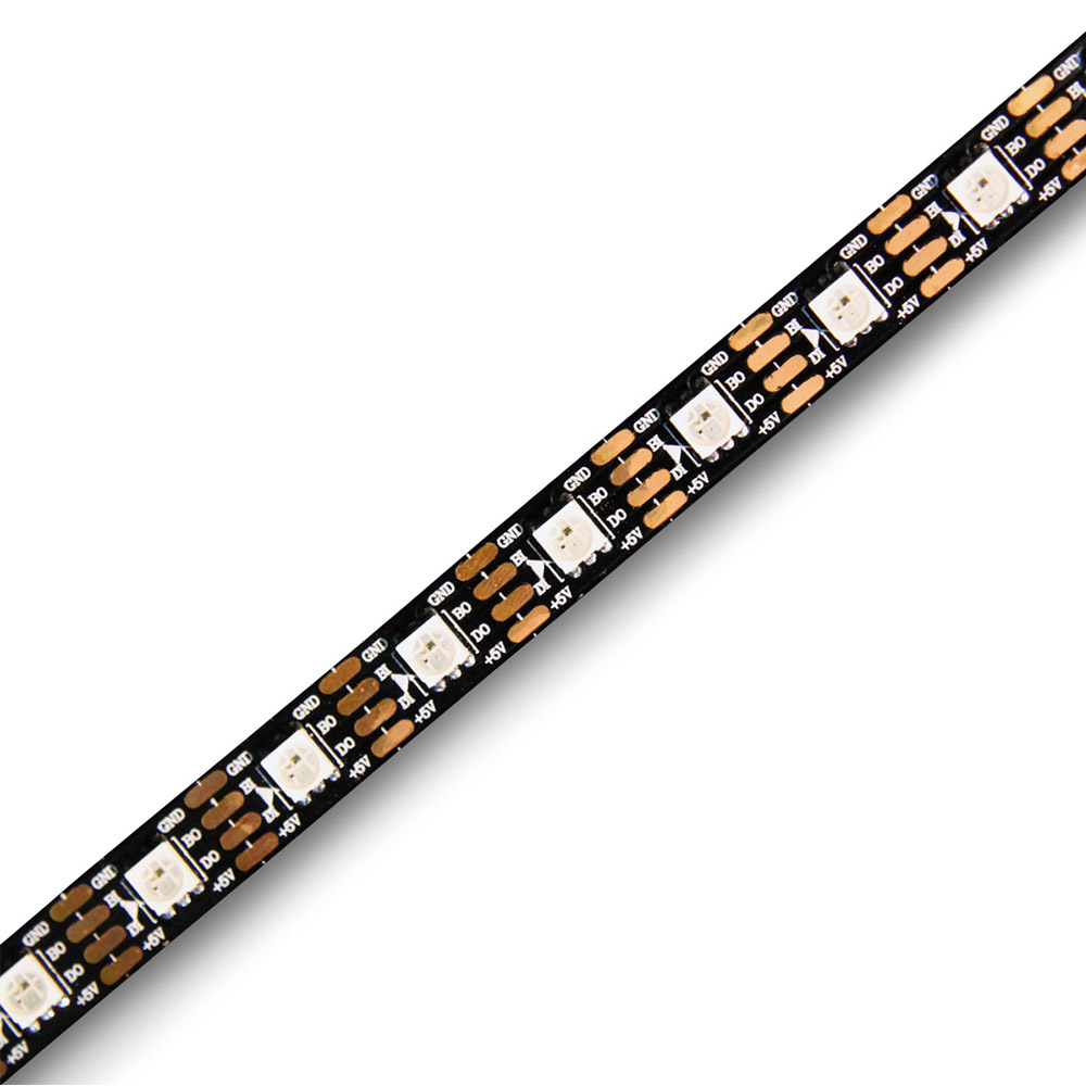
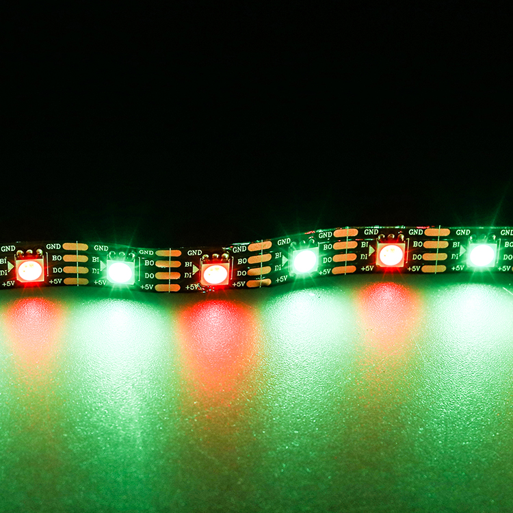
The current LIKELIGHT L-S-WS2813-10060 page identifies DC5V, WS2813 dual signal, RGB and 60 LEDs/m.
It is a candidate for evaluating dual data paths in cabinets or dynamic installations, provided compatible control settings and sample tests use the actual wiring and load.
For the hypothetical three racks, dual signals and three independent service zones are separate decisions: dual-signal strips can be used within each zone, with separate data outputs and isolatable power establishing maintenance boundaries.
Power, dimensions and protection follow the final SKU; no unverified value is used here to size a supply.
| Parameter | Value |
|---|---|
| Model | L-S-WS2813-10060 |
| Operating voltage | DC5V |
| Light colour | RGB |
| Data architecture | WS2813 dual-signal data backup |
| LED quantity | 60 LEDs/m; not a pixel or cutting calculation basis in this article |
Make quotations comparable
- Project and outage boundary: Supply zone lengths, access arrangements and the zones that must keep playing to define cascade versus independent outputs.
- Control and power information: Supply controller model, output settings, programme, feeder lengths and measured load to define mapping, power paths and protection.
- Requested purchasing documents: Request the exact SKU, valid option matrix, connection and installation drawings, itemised BOM, sample acceptance plan, matching spares and lead time. These are quotation requests, not promises that every option is available.
Separate strip supply, system accessories and field work, and compare arrangements against the same acceptance conditions. Spare interfaces and lead times affect recovery time and should be settled before a failure.
Buying questions
Can backup data fix tail colour shift?
Not directly when the cause is power loss. Measure loaded voltage under the actual programme, then inspect data and colour mapping.
Do two power supplies make two independent zones?
No. Check shared upstream data, actual power isolation and common controller failure points. Do not directly parallel positive terminals of different supplies without an engineered design.
Can a failed-LED count be guaranteed?
The chip name cannot establish a complete-package guarantee. Agree on the sample, wiring and safe simulated fault, then record behaviour under those conditions.
Can 60 LEDs/m determine cutting length?
Verify LED quantity, controllable pixels and cutting positions separately. Use physical pad markings and final drawings, not density-derived cutting lengths.
Chip manufacturer reference: Worldsemi WS2813 dual-signal family
Copy-ready enquiry
We plan DC5V WS2813 RGB strips in [environment] across [zone count and lengths], displaying [programme and brightness]. Our controller is [model/settings], feeders are [routes/lengths], and we require [acceptable outage area/access].
Please compare a continuous dual-signal cascade with independent service zones and return the exact SKU, valid option matrix, drawings, itemised BOM, sample acceptance plan, matching spares and lead time, separating supply from field-work scope.


