RGB Sign Modules Still Fail After Replacement? Commissioning Tests and System Purchasing
Imagine a lightbox that previously ran a chase correctly. After fitting similar-looking RGB modules, red and green are reversed; another branch dims at the end when brightness rises.
Buying more lookalike replacements can mistake a control setting or power-path problem for failed lights.
For a sign installer, the real decision is whether to replace one module, repair a branch connection, or purchase modules, controller and supply as a complete system.
Repeatable comparison tests should determine that choice, not the cheapest component.
Where to start
- Preferred approach: Establish a reference with a known-good short sample string and a fixed test programme. Change one variable at a time, locate the problem in the module, branch or configuration, then order.
- Separate colour from interruption: A consistent red/green swap across the whole string points first to colour mapping. Failure after a particular point points first to data and connections around that boundary; darkness alone does not prove a failed module.
- Stop conditions: Do not connect further modules if pin assignment, polarity or voltage differs, if a replacement fails primary-colour and chase tests on the reference bench, or if abnormal heating occurs. Disconnect power before changing connections.
For the first enquiry, send a fault video, original module and controller labels, installed quantity and wiring photographs.
These distinguish matching spare parts from a new system; complete drawings can follow once the direction is agreed.
Three hypothetical tasks lead to different purchase decisions
- Hypothetical task A: wrong colours after replacementTwo modules are replaced in an existing sign string, and the new positions turn green during a red test. Establish whether their colour behaviour matches the existing batch rather than rewriting the whole programme to hide the difference.
- Hypothetical task B: the chase stops midwayThe short reference string works, but the installed string stops responding after a connector. Separate upstream output, the connector, downstream modules and the configured pixel count to identify a replaceable fault boundary.
- Hypothetical task C: the end changes at high brightnessLow output works; at high output the end dims or changes colour. Compare loaded voltage at the supply and end under the same programme with a separate short branch before choosing connector repair, power-distribution changes or replacement.
Build a reference that separates colour from sequence
RGB data sends separate colour components to the driver.
Incorrect mapping can send the requested red value to another colour channel; a complex animation changes colour, brightness and timing together, making the faulty variable difficult to identify.
Hold the configuration fixed, send solid red, green and blue in turn, then move one chase point through the module sequence to check colour and order separately.
Three LEDs describe light emitters, not automatically three independent pixels.
If all modules consistently swap the same primary colours, check the controller colour-mapping setting first.
If only new modules differ, compare old and new samples on the same reference bench and favour replacements with matching colour behaviour.
The moving point establishes actual control grouping: record which LEDs respond to one control step, then set the pixel count from that grouping. Do not install a sample that fails the expected colour or grouping tests.
A chase breaks midway: locate the data boundary
A cascaded driver receives and forwards subsequent data, so illuminated upstream modules do not prove that downstream modules receive valid data.
Failure after one point can come from a broken connection, an output fault at that position or an insufficient programme length; loss of downstream power can also look like black modules.
Locate the boundary between the last correct response and first incorrect response instead of replacing everything from the controller onward.
First compare the programme pixel count with the grouping established on the sample. With power disconnected, check connections and data direction at both sides of the boundary.
Test a short downstream section on the verified control-and-power reference, and a known-good short section on the original boundary output.
If the downstream section works on the reference but the good section fails at the original boundary, prioritise upstream output or boundary wiring. Otherwise narrow the investigation to the downstream section.
Change only one item at a time so a temporary recovery is not mistaken for a lasting repair.
Failure at higher brightness: compare loaded conditions
Cables, connections and return paths have resistance; voltage loss can be understood as ΔV=I×R. At unchanged loop resistance, higher current increases the loss.
Brightness-related symptoms therefore justify checking the power path first, but do not prove a power fault alone: signal quality or a damaged driver can also vary with operating conditions.
An unloaded supply reading cannot replace voltage measured at the running end of the installation.
At a fixed programme and brightness, record loaded voltage at the supply output, branch entry and end, and compare with the short reference branch.
If the short branch works while the installed end has substantial loss, locate cable and connector losses before reassessing power distribution.
If the fault follows the same module under comparable loaded conditions, investigate that module first.
Do not arbitrarily raise the supply voltage of a DC12V system to cure the end, and do not accept recovery at lower brightness as complete commissioning.
Replacement acceptance must show what the fault follows
Similar appearance, LED count and a connector that fits show only possible mechanical matching. Driver type, polarity, actual pin assignment and colour behaviour determine electrical and control compatibility.
Moving the suspect module to a known-good position and a good module to the fault position reveals whether the symptom follows the part or remains in the branch.
Changing controller, supply and wiring together removes the diagnostic value of the comparison.
Cross-substitute only after voltage, polarity and interface definitions agree, and disconnect power for every change.
If the suspect remains faulty on the reference and the good replacement restores the original position, focus purchasing on matching spares. If both modules fail only on the original branch, prioritise branch repair or controller settings.
Repeat primary-colour, chase and target-brightness tests, including power cycling and retesting after reconnection; record the actual behaviour as the sample acceptance evidence.
A complete purchase cannot be compared on module price alone
Pixel modules need a matching control output; an analogue RGB dimmer is not the same device as a cascaded-data controller.
Installed cost also includes supply, distribution protection, cable and connectors, commissioning and compatible spares. A field replacement must allow resealing and maintenance access.
An IP67 body does not automatically give a modified field joint the same protection.
For a local repair with an existing system that passes reference testing, purchase matching modules, connections and an appropriate spare stock.
For a first installation or components that cannot pass together, quote the controller, programme configuration, power circuits and modules as one system.
Include connector sealing, end treatment and installation conditions in outdoor sample acceptance. Do not approve immersion, corrosive exposure or an inaccessible installation from an IP67 label alone.
Compare quotations using the same system boundary before comparing unit prices.
A loaded comparison: turn readings into a purchase decision
Prioritise locating feeder or branch loss and exclude a module fault by cross-substitution, rather than immediately buying a larger supply or replacing every light.
After repair, retest at target brightness; accept colour, sequence and installed loaded behaviour together.
Compare complete cost as Ctotal=Cmodules+Ccontrol and supply+Ccable, connectors and protection+Cinstallation and commissioning+Cspares and logistics.
A quotation omitting the last four items can have a low module price without a low installed cost.
All readings below are hypothetical diagnostic inputs, not product test results.
The measured object is one independent DC12V feeder from the supply to a load distribution point, with no intermediate taps and a steady 4.8A flowing through its entire length.
Under a fixed high-output programme, the supply end reads 12.0V and the distribution point 10.8V at the same steady load; the difference includes outgoing and return paths.
A separate short reference branch with compatible samples and the same configuration passes primary-colour and chase tests.
Current is not derived from LED count, packaging quantity or nominal power; no minimum module operating voltage is assumed.
Hypothetical task C: readings and interpretation
-
Independent feeder voltage loss
Formula or observation
ΔV=12.0−10.8=1.2V; 1.2÷12.0×100%=10%Purchasing implication
10% describes this hypothetical measured loss, not an allowed drop or failure threshold. Investigate the power path before replacing modules in bulk. -
Equivalent feeder loop resistance
Formula or observation
R=ΔV÷I=1.2÷4.8=0.25ΩPurchasing implication
Valid only for this untapped feeder carrying 4.8A throughout, including outgoing and return paths. A distributed module string cannot use total inlet current this way to derive actual wire resistance; segment measurements are still needed to locate loss. -
Cross-substitution
Formula or observation
Move the suspect to the reference bench; move a good module to the original positionPurchasing implication
Buy matching spares if the symptom follows the part. Allocate the budget to wiring, power or control repair if it stays in the branch.
Symptoms and purchasing direction
| Site condition | Choice and acceptance |
|---|---|
| All modules consistently swap red and green | Check global colour mapping first, only changing settings when compatibility is established; do not conceal new/old differences in the programme. |
| Only new modules show wrong colours | Compare batches on the same reference bench and choose spares matching primary-colour behaviour and actual control grouping. |
| Replacement restores a dry indoor installation | Purchase within the local repair scope after repeat colour, chase, target-brightness and restart tests pass. |
| An outdoor replacement requires new joints | Accept resealing, end treatment and service access together; body IP67 alone does not approve the installation. |
| The end fails at high brightness | Measure entry and end under load and isolate path loss before upgrading supply or replacing modules in bulk. |
| Even the good short string does not respond | Check data-controller type, pin assignment and configuration; jointly validate compatible controller and samples before purchasing a system. |
The LIKELIGHT SM16703P module as a replacement or system candidate
The current LIKELIGHT page for L-M-DC12V-SM16703P lists DC12V, RGB, SM16703P, SMD5050, 70×12mm, 20 modules/string and IP67, and describes programmable chase and gradient applications.
It is a sample candidate for dynamic RGB signage: validate primary colours, chase and actual control grouping on a short reference bench before deciding its replacement relationship with an existing system.
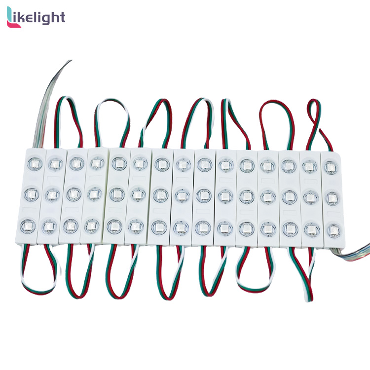
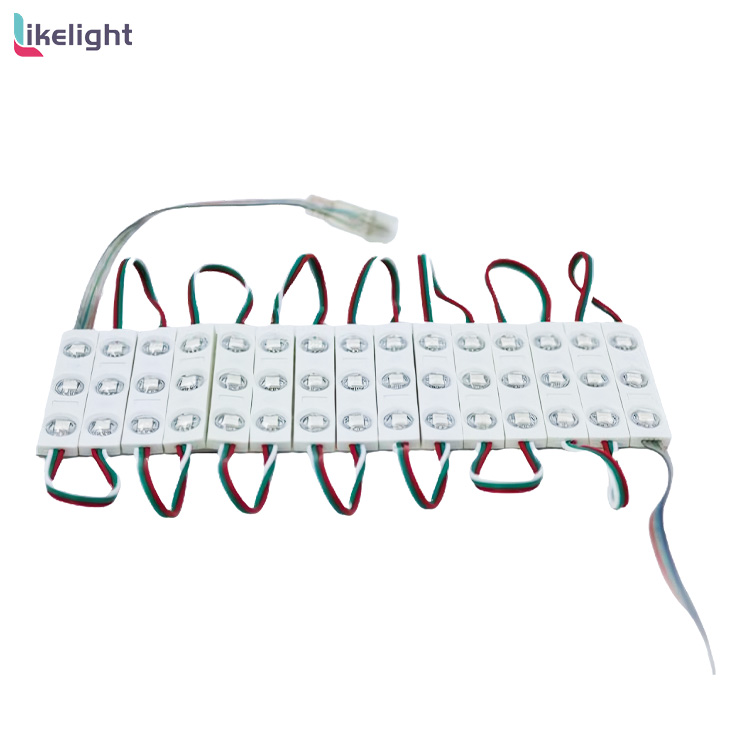
The title and photographs show three LEDs per module. This does not mean three pixels or prove interchangeability with every similar RGB module.
Twenty modules per string is the published supplied-string quantity, not this article's promise of controller-port capacity or safe feed length. For signs requiring only fixed white, compare a white-light solution first.
For detailed close-view text or video, select a product with established pixel density and display construction rather than using three LEDs as a proxy for display capability.
The two full photographs identify body shape, LEDs and string arrangement. They are not pinout evidence, ingress test results or proof of electrical compatibility. Accept the actual sample with its matching system.
| Parameter | Current configuration |
|---|---|
| Model | L-M-DC12V-SM16703P |
| Operating voltage and colour | DC12V; RGB |
| Driver and LEDs | SM16703P; SMD5050; three LEDs per module |
| Published body dimensions | 70×12mm |
| Supplied string quantity | 20 modules/string |
| Body protection | IP67; field joints and modified installation assessed separately |
Make the quotation match the fault, not just the quantity
- Fault and existing equipmentSend colour or chase fault video, the original module label and controller model to distinguish mapping, incompatible replacements and branch faults instead of quoting an unsupported full replacement.
- Wiring and environmentSend module order, branches, supply positions, cable lengths, pin definitions and installation photographs to define connectors, protection, resealing and maintenance scope.
- Quantity and acceptanceSpecify installed quantity, target brightness, animation and an acceptable sample test method to define test strings, spares and batch-consistency acceptance.
- Required quotation outputsRequest exact SKUs and a valid configuration matrix, polarity/data-direction drawings, a controller-and-supply system BOM, sample acceptance criteria, spare configuration, lead time and itemised costs. These are requested outputs, not unverified stock or service promises.
Identify retained and replaced parts and who supplies programme configuration and site retesting. Compare local repair and a new system only against the same BOM and acceptance scope.
Purchasing and commissioning questions
Can an ordinary RGB controller drive SM16703P modules?
An analogue RGB dimmer adjusts colour circuits; a cascaded-pixel controller sends sequential data. RGB in a name does not establish the control type.
Use a controller explicitly supporting the driver and output method, then verify this batch on a sample; a connector that fits does not establish compatibility.
Should three LEDs be configured as three pixels?
Do not set the count from LED quantity. Primary colours verify colour; a moving chase point establishes which LEDs respond to one control step. Record pixels from actual grouping.
Three light emitters do not automatically form three control units.
Is one successful power-on enough to order a batch?
No. Test red, green, blue, a moving chase point and loaded behaviour at target brightness, then repeat after restart and reconnection. Record colour, order, grouping and fault positions.
Reject inconsistent replacement behaviour as interchangeable spares. Agree test duration in the project acceptance plan; one power-on does not prove lifetime or reliability.
When should we stop buying lookalike modules?
Change direction when pins, polarity or voltage differ, samples fail the same reference tests, or the requirement is fixed white, detailed video or unassessed immersion.
Identify the needed control, optical or environmental capability and select the corresponding system.
Does a dim end always need a larger supply?
No. More supply capacity does not remove cable or connector resistance; data or modules can also cause the fault. Compare entry, end and short reference branch under the same programme, then cross-substitute.
Evaluate a supply upgrade only after proving capacity is the limiting factor.
SM16703 data control type: Advatek controller-manufacturer guidance
Ready-to-use project enquiry
We need to address [wrong colours/chase interruption/high-output end failure] in [sign/lightbox]. Existing modules: [model]; controller: [model and settings]; installed quantity: [modules].
Fault video, wiring and installation photographs are attached. Please first assess [matching spares/local repair/complete system] and quote a sample.
Please provide exact SKUs and a valid configuration matrix, pin/polarity and data-direction drawings, a controller/supply/cable/connector/protection BOM, sample acceptance criteria for primary colours, chase and target brightness, spares, lead time and itemised pricing.
We will compare samples on the same reference bench and retest on site before deciding the purchase.