WS2813 Backup Data Factory Acceptance: Prove Fault Continuity Before Installation
A dual-signal strip should be accepted with a controlled primary-data interruption, not only a color chase. This guide separates backup-path proof from DC5V power and controller faults for the 60 LEDs/m LIKELIGHT strip.
Backup data is a signal-continuity feature, not a substitute for correct power distribution, common reference, controller setup or waterproofing. A useful factory test must isolate those failure classes.
Quick answer
- Backup data improves continuity under specified pixel-path faults; it does not back up power or ground.
- 60 LEDs/m gives a theoretical 16.67 mm LED pitch.
- Power is not published, so measure the released strip before sizing DC5V circuits.
Published facts
| Model | L-S-WS2813-10060 |
|---|---|
| Input | DC5V |
| Control | WS2813 dual-signal cascade |
| LED system | Addressable RGB |
| Density | 60 LEDs/m |
| Viewing angle | 120 degrees |
Build the acceptance test around one intentional data fault
Run a known effect on a representative branch, record the normal output, then interrupt only the primary data path at an agreed test position. Downstream behavior is evidence for the backup path only when DC5V and ground remain intact.
Restore the path and repeat the test after power cycling. Record connector orientation, data direction, controller profile and the exact test position so production and site teams can reproduce the same result.
| Test stage | Pass evidence |
|---|---|
| Baseline | All pixels follow the known effect before interruption |
| Primary-data fault | Recorded downstream behavior with power unchanged |
| Restoration | Normal output returns after the path is restored |
| Repeatability | A second branch reproduces the documented result |
A color chase cannot prove the backup path
A normal animation proves that power, controller and at least one data route work together. It does not prove that the second route will carry the stream after a primary-path interruption.
The acceptance record must therefore create one controlled fault while holding all other variables constant. If power or ground is disturbed at the same time, the result cannot diagnose backup-data continuity.
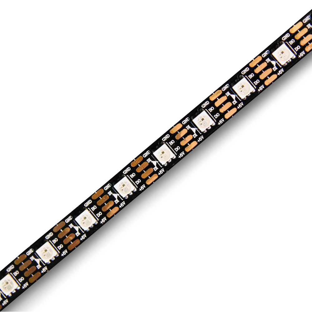
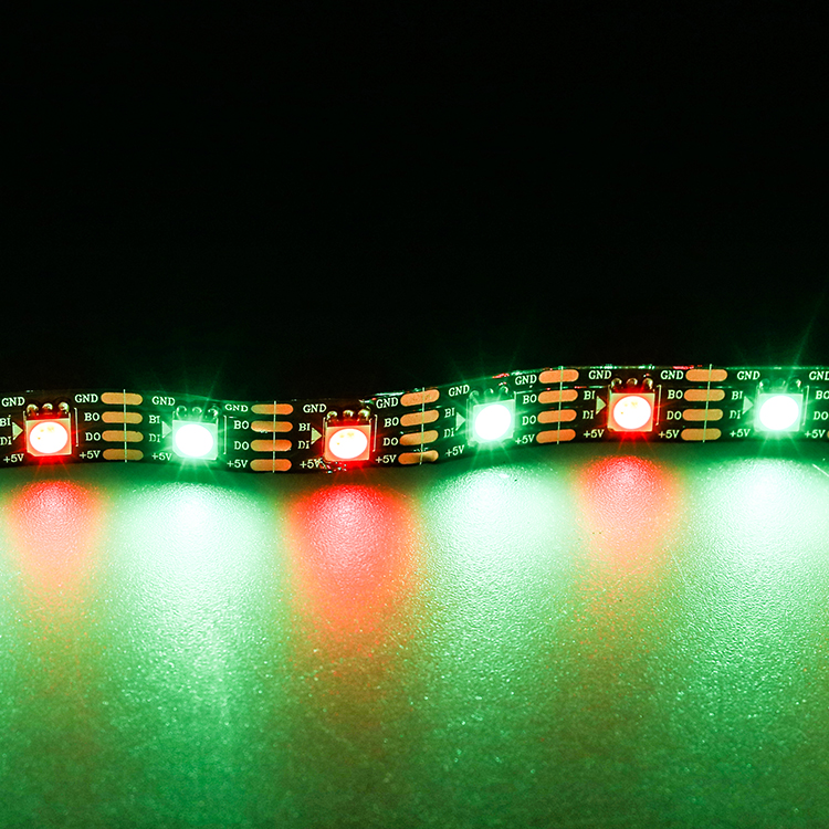
Test WS2813 as primary data plus backup data
The page publishes WS2813 and a dual-signal data-backup design. Plan the wiring and controller profile for this topology; do not label the second line as a clock line or treat it as a second independent animation channel.
A passed bypass test does not mean every possible failure can be crossed. The documented test position and finished-strip pad arrangement define what was actually proven; damaged power conductors and multiple adjacent faults remain different cases.
Keep DC5V voltage-drop testing separate
The reviewed page confirms DC5V but does not publish a reliable power value for this exact configuration. Current, injection spacing and supply quantity therefore cannot be calculated from the page without inventing an input.
Measure current and end voltage on the approved sample under the intended effect. A downstream blackout that changes with brightness or improves after power injection points to power distribution, not proof that the backup-data architecture failed.
Use 60 LEDs/m to judge detail, not electrical capacity
The published density gives a nominal LED pitch of 1000 ÷ 60 = 16.67mm. This supports spacing and effect decisions, but it does not establish a maximum run, feed distance or controller capacity.
A one-metre mock-up can reveal whether the pixel rhythm is suitable at the real viewing distance. Freeze PCB width, protection construction and reel configuration from the approved sample because those values are not reliably established by the reviewed page.
Project decision table
| Condition | Decision | Reason |
|---|---|---|
| One failed pixel path | Evaluate WS2813 backup data | Test the released wiring |
| Controller mismatch | Do not expect backup recovery | Protocol compatibility is separate |
| Long DC5V layout | Create measured power zones | Power is not published |
| Close-view animation | Assess 16.67 mm pitch | Optics and content still matter |
| Wet installation | Confirm a protected version | Protection is not published |
| Bulk order | Approve a fault-injection sample | Document expected recovery |
Where LIKELIGHT L-S-WS2813-10060 fits
LIKELIGHT model L-S-WS2813-10060 is a candidate for signage, architectural accents and dynamic decorative lines that need addressable RGB and an added data-continuity path. Re-evaluate it when DC5V distribution cannot be zoned, the controller cannot support WS2813, or the project expects backup data to replace proper power and connector design.
Information required before quotation
- Layout and zone lengths
- Closest viewing distance
- Target animation or logo
- Controller model and mapping
- Power locations and cable route
- Environment, quantity and schedule
FAQ
Does backup data keep the strip on after power loss?
No. It is a data-continuity feature, not redundant power.
Is every fault bypassed?
No. Verify the specified behaviour on the released sample.
Can current be calculated from DC5V?
No. Rated power or measured current is also required.
Is 60 LEDs/m the cutting interval?
No. Cut only at marked copper pads.