

Will 20×20 mm RGB Neon Flex Fit Your Sign Channel? Check Section and Viewing Face
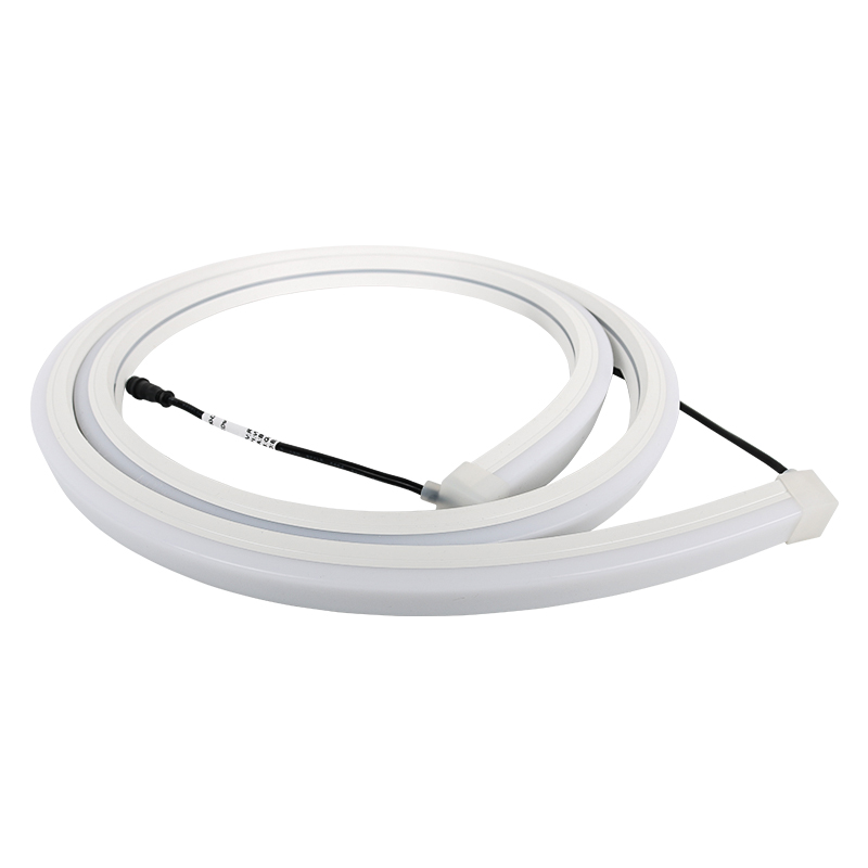
When neon flex sits inside a sign channel, first check its envelope and emitting-face direction—not just the RGB effect. LIKELIGHT's L-N2020 page lists 20×20 mm, DC24V and programmable RGB; final fit still needs a section drawing and a sample.
30-second selection answer
- Worth shortlisting: A sign channel can accommodate a nominal 20×20 mm body, needs a wide-angle RGB line, and can be checked before fabrication is released.
- Send these first: Share channel width/depth, intended viewing face, finished lengths and curves; request the exact section drawing and a sample.
- Hold batch approval: Do not release from the nominal size alone if tolerance, bend plane/radius, cable exit or mounting clips are unconfirmed.
Send the channel CAD or section dimensions and the intended viewing direction for a first fit screen.
Which lit face will the channel reveal?
Whether a sign reads as a bright line or hides behind the lip depends on the lit face, aperture and viewing direction together. A diffuser may make the tube appear continuous, but it cannot preserve the same visible width in every recess.
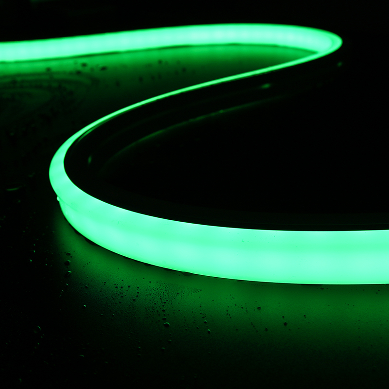
The L-N2020 listing says 'top side lighting' and describes a typical wide/180-degree view. Neither is a dimensioned orientation drawing. Mark the sign's front and oblique sightlines on one section with the lit face; if its position remains unclear, inspect a mounted sample from both views.
How does 20 x 20 mm compare with clear channel space?
The listed 20 x 20 mm is a nominal body section, not a recommended channel width or depth. Maximum body size, tolerance, clips and cable exit use space in different directions; a deep setback can also hide the bright face behind the lip.
Measure actual clear width and depth, not the nominal opening on the fabrication plan. Compare a dimensioned drawing for this build with the mounting path, aperture and future removal space. If one fails, revise the channel or compare a smaller profile.
Can the line follow the intended corner?
A flexible-looking tube does not establish which way it may bend. The bend plane relates to the lit face and internal strip; a wrong bend can twist the line, while end caps and cables occupy the corner. The L-N2020 listing gives no minimum radius or permitted bend plane.
Put the tightest radius and each turn on the installation drawing. Obtain the allowed bend direction, radius and termination detail for the exact build, then trial the real corner. If it fails, change the route or profile; the curved product photo is not a radius specification.
When can RGB control and power be specified?
Programmable RGB describes changing colour, but the visible listing leaves pixel pitch, IC, protocol and wattage unspecified. RGB or DC24V alone does not determine controller ports, animation detail, supply size or cut intervals; a control segment is not automatically a cut unit.
Uniform colour along a sign and a chase around its outline are different briefs. State the desired animation and each finished length. Request the matching control/cut drawing and W/m, then plan the controller and feeds using those actual values.
What should the mounted sample prove?
A body that enters the straight channel may still fail at an end cap, connector or cable turn. Outdoor work must include the exposed termination and connection; the captured page does not provide a filled IP rating for this model.
Fit a sample in a real channel section. Check the line from the intended view, the end and cable space, and removal for service. Outdoors, obtain protection information for the selected assembled body and ends; do not copy another neon model's IP claim.
A quick buyer-side check
Buying outcome: 4 mm is not fit approval. Request maximum envelope/tolerance and clip drawings. If actual assembly or service clearance is inadequate, revise the channel or choose a smaller section before ordering a sample.
Assume a channel has 24 mm clear width and the body is nominally 20 mm wide: 24−20=4 mm total nominal clearance, or about 2 mm per side if centred. This excludes tolerances, clips and cable exit.
Worked check (illustrative assumptions, not a product test)
-
Nominal space
Parameter
24 - 20 = 4 mm overallBuying decision
Then check clips, tolerances, cable and depth
Conditional selection
| Project condition | Buying decision |
|---|---|
| Straight channel with generous space | Shortlist L-N2020 for drawing and sample fit; check depth and visible face too. |
| Channel close to 20 mm | Nominal width cannot approve fit; compare maximum body, clips and cable exit. |
| Curved or returning route | Check the permitted bend plane and radius before fixing the path. |
| Viewed mainly from the side | Check the lit face and possible masking on drawing and sample; top-side wording does not prove equal brightness. |
| Long runs | Obtain W/m and wiring before sizing feeds. |
| Outdoor or animated signs | Check assembly protection and the actual controller protocol. |
A LIKELIGHT configuration to evaluate
L-N2020 is a candidate for a channel with room for the section and a desired RGB line effect: the page lists 20×20 mm, DC24V, programmable RGB and a typical wide/180-degree viewing description.
Before a batch, confirm maximum dimensions/tolerance, emitting-face orientation, bend limits, control architecture, power, IP and end construction. Use the exact drawing and a sample to check channel fit, view angle and ends, then freeze the BOM.
| Parameter | Published value |
|---|---|
| Model | L-N2020 |
| Nominal section | 20×20 mm |
| Supply | DC24V |
| Colour/effect | Programmable RGB |
| Viewing description | Typical wide/180-degree wording; verify actual orientation on the drawing |
| Not stated on page | Pixel pitch, power, protocol, IP, minimum bend radius |
Prepare a comparable RFQ
- ChannelSend section CAD/width/depth, panel thickness and service space.
- AppearanceMark viewing direction, emitting face, target brightness and background.
- RouteGive finished lengths, curve locations and required minimum radius.
- Electrical/controlState voltage, controller/protocol and effect; request power and wiring data.
- Supply scopeAsk for exact SKU/options, dimensional/wiring drawings, BOM, sample/acceptance plan, system quote, spares and lead time.
The reply should identify one buildable configuration so the buyer can compare installed scope, not just unit price.
Buyer questions
Is 20×20 mm the channel size to design?
No. It is the nominal section; allow for tolerance, clips, cable exit and service access.
Does 180° mean identical brightness in every direction?
Do not assume that. It is a typical wide-angle description; confirm orientation and obstruction on drawing and sample.
Can I order to a minimum bend radius?
The page does not state one. Send CAD, request written limits and approve a sample before fixing the route.
Copy-ready project inquiry
Please review sign-channel fit: CAD/width/depth [ ]; viewing face [ ]; finished lengths [ ]; curves/minimum radius [ ]; supply and controller [ ]; destination country [ ]. Return the exact L-N2020 section/wiring drawings and limits, a complete quotation, and a representative sample proposal for fit and viewing checks.