


How to Specify 35mm UCS1903 RGB Pixel Lights for Amusement Rides: Pitch, Load and Serviceability
A ride outline can look uneven even when every pixel works. The usual causes are a centre pitch chosen without viewing tests, too many points placed on one service zone, or power and data branches that cannot be isolated when one section needs maintenance.
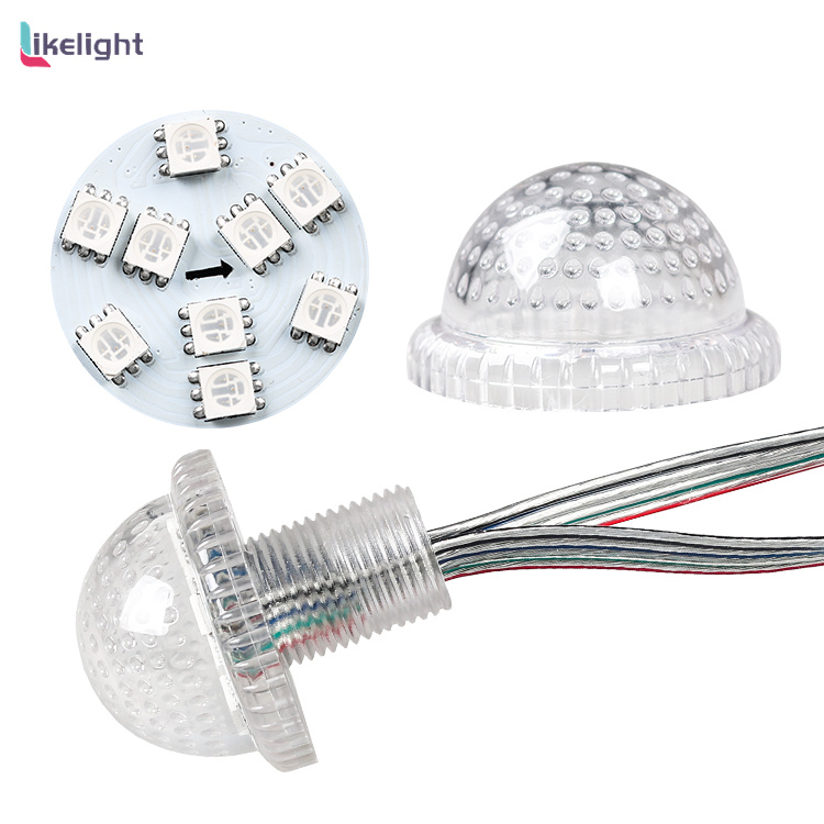
This article uses the published LIKELIGHT L-D-359-N12V/24V configuration: a 35mm full-color point light with UCS1903 cascade control, DC12V/DC24V variants, listed 1.44W and 2.16W power values, IP66, -40°C to +60°C operation, CE and RoHS. The page does not map each power value to a voltage version, so the calculations use a transparent range instead of inventing a pairing.
Published product facts
| Published item | Value |
|---|---|
| Model | L-D-359-N12V/24V |
| Point format | 35mm full color ICRGB |
| Control IC | UCS1903 |
| Voltage options | DC12V / DC24V |
| Listed power values | 1.44W / 2.16W; version pairing not published |
| Protection | IP66 |
| Operating temperature | -40°C to +60°C |
| Published documents | CE and RoHS |
| Warranty | 2 years |
Start with viewing distance, not the 35mm body size
The 35mm dimension describes the point-light body, not the installation centre pitch. A 50mm pitch creates 20 points per linear metre, 75mm creates about 13.3, and 100mm creates 10; these are layout scenarios for mock-up comparison, not published mounting rules.
Closer spacing can make curves and letters read more smoothly at short range, but it also increases point count, data load, connectors and service work. Distant ride outlines may accept a wider pitch. Test a representative section against the actual background and normal viewing path before freezing the drilling pattern.
Read the 12V/24V and 1.44W/2.16W options correctly
The product page lists DC24V/12V and two consumption values, 2.16W and 1.44W, but does not state which value belongs to which voltage version. They should therefore remain separate published options until the sample or order sheet links the voltage and power.
Do not assume that voltage determines brightness, point spacing or UCS1903 behavior. For this model, the selected voltage must match the project power architecture, while color output, wiring and final electrical data must follow the approved version.
Estimate project load as a range before the version is frozen
Using the two listed power values as a range, 100 points represent 144W to 216W and 500 points represent 720W to 1080W. This provides a useful early load envelope without assigning either value to DC12V or DC24V.
Current cannot be calculated responsibly until the approved power-to-voltage pairing is known. After that pairing is frozen, divide the installation into serviceable circuits, include cable and connector losses plus project margin, and verify end-of-branch voltage under the intended full-color program.
Project selection table
| Project condition | Decision direction | Why |
|---|---|---|
| Tight letters or curves | Test 50-75mm centre pitch | More points may improve short-range shape definition but increase load and service work. |
| Distant ride outline | Compare 75-100mm centre pitch | A wider rhythm may remain readable and reduce point count. |
| Existing DC12V system | Evaluate the DC12V version | Freeze its matching power value and wiring before current calculations. |
| Existing DC24V system | Evaluate the DC24V version | Do not infer its power from the order of values on the page. |
| Programmable effects | Use UCS1903-compatible cascade control | Plan pixel mapping and data direction rather than individual DMX addresses. |
| Outdoor service | Use zoned branches with accessible connectors | IP66 at the point does not remove joint and enclosure planning. |
Plan UCS1903 as a cascade-pixel system
UCS1903 indicates cascade-pixel control. Plan pixel count, data direction, output-port allocation, mapping order and branch layout; do not describe each point as requiring an individually set DMX address unless the upstream controller explicitly maps the pixels into DMX or Art-Net channels.
A control segment is not automatically a cutting or removable unit. For a point-light system, serviceability depends on connectors, branch boundaries and physical access. Confirm the controller, signal output, pinout and replacement method on the released wiring drawing.
Treat IP66 as one part of the outdoor installation
The page publishes IP66 for this model and an operating range of -40°C to +60°C. Those facts support evaluation for exposed ride and sign applications, but they do not automatically qualify every field connector, branch joint, cable exit or power enclosure.
Plan cable strain relief, connector orientation, drainage, vibration clearance and access to replace a point without dismantling a large panel. The page also lists CE, RoHS, a 50,000-hour value and a two-year warranty; certification documents and warranty scope should correspond to the final ordered configuration.
Where the LIKELIGHT 35mm RGB point light fits
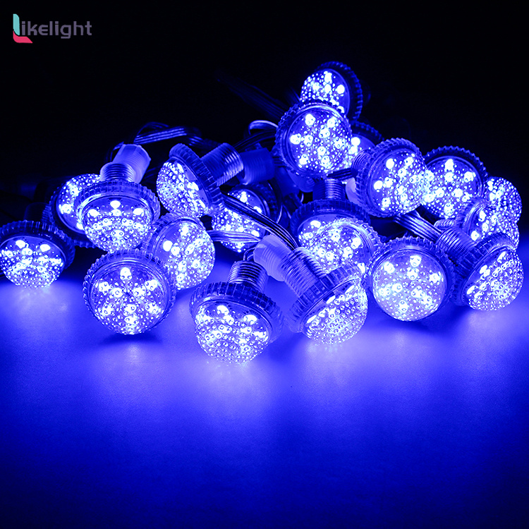
Model L-D-359-N12V/24V can be evaluated for amusement-ride outlines, letter signs, logos and decorative point arrays that need visible full-color nodes and UCS1903 cascade control. The 35mm format offers a smaller point than large fairground bulbs, which can help tighter curves when the tested centre pitch and viewing distance support the design.
It is not the first choice for a continuous neon-like line, very high-resolution video or a project that cannot provide access to branches and connectors. Those applications should compare neon flex, a denser pixel format or a serviceable modular structure rather than relying on point count alone.
Suitable when
- Visible RGB nodes for rides, logos and exposed-letter layouts
- Projects that can zone power and data branches
- Layouts where a 35mm point is verified by a mock-up
Re-evaluate when
- Continuous neon-like light lines
- High-resolution video surfaces
- Installations with no access to connectors or branches
Information to send before quotation and sampling
Provide the ride or sign drawing, point quantity by zone, proposed centre pitch, closest viewing distance, target animation, DC12V or DC24V system preference, controller model, branch layout, connector direction, outdoor exposure, maintenance access, sample quantity and schedule.
These inputs let LIKELIGHT evaluate the point rhythm, total load range, data mapping and service zones together. The approved sample should record the exact voltage-power pairing, pinout, controller file and protection details before bulk production.
- Ride, sign or logo drawing
- Point quantity and centre pitch by zone
- Viewing distance and animation reference
- DC12V or DC24V system preference
- Controller, mapping and branch plan
- Connector direction, exposure, sample and schedule
Frequently asked questions
Does a 35mm light require 35mm centre spacing?
No. The housing size and centre pitch are separate; verify fixing clearance and visual rhythm.
Can the current be calculated from the page?
Not yet, because the page does not map 1.44W and 2.16W to the DC12V and DC24V versions.
Is UCS1903 the same as DMX512?
No. UCS1903 is cascade-pixel control; DMX or Art-Net only applies when an upstream system maps the pixels.
Does IP66 cover every field connection?
No. Joints, cable exits, branches and enclosures require their own complete protection plan.


