How to Plan RGB LED Modules for Channel Letters: Spacing, Power and Pixel Mapping
A sign module can be waterproof and still produce dark strokes, overloaded feeds or reversed effects when module spacing and data order are decided on site. This guide uses the published 70×12mm, DC12V, 0.96W, SM16703P, 20pcs/string and IP67 facts to build a testable sign layout.
The common failure begins with spacing, not with colour
A narrow letter stroke can receive too many modules and show bright patches, while a deep or wide cabinet can remain dark between rows. The 70×12mm body tells the installer what physically fits, but it does not publish a universal coverage area or centre spacing.
Build one representative letter or cabinet section with the final face material, depth and internal reflectance. Approve uniformity from the real viewing distance, then use that tested spacing to estimate the remaining letters.
Three LEDs and a 70mm body affect the layout
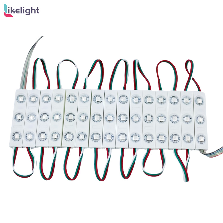
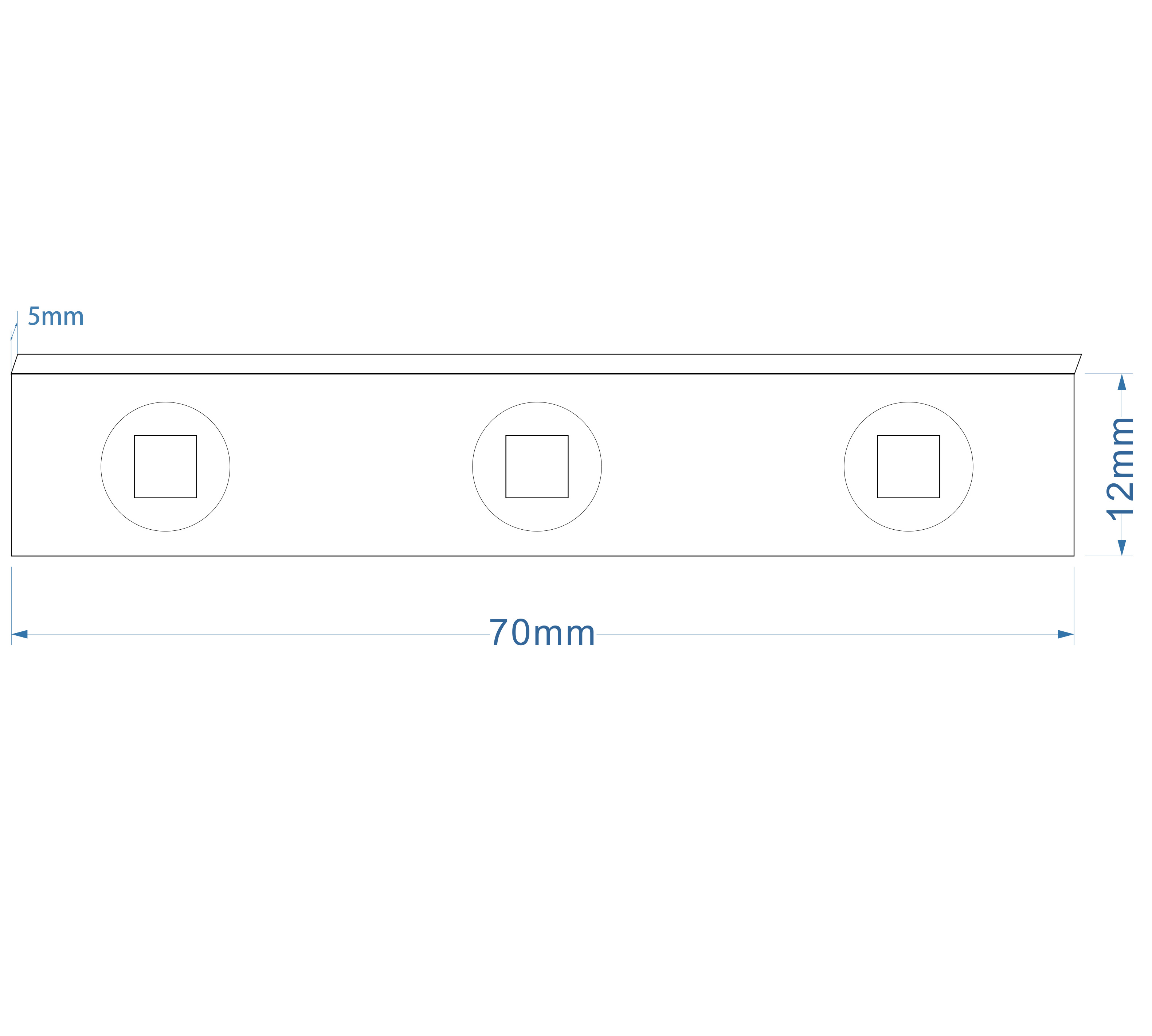
The page publishes three SMD5050 LEDs in a 70 × 12mm injection-moulded module. Three emitters spread light along an elongated body, which can suit strokes and sign cabinets where a single-point module would require more pieces.
Module orientation, distance to the sign face and row spacing still control uniformity. At corners, keep the light pattern continuous without forcing wires or placing a module where it blocks drainage or service access.
Calculate string load before deciding circuit size
Each module is published at 0.96W and DC12V, so theoretical current is 0.96 ÷ 12 = 0.08A. For the published 20pcs/string, load is 20 × 0.96 = 19.2W and current is 1.6A before cable loss and power-supply margin.
That calculation does not establish a maximum number of strings per feed. Divide large signs by letters or serviceable zones, then size cable, connectors, protection and power supplies from the final module count and route length.
SM16703P mapping must follow the installed order
The page identifies SM16703P, RGB full colour and four-wire red, green, blue and black male/female connectors. It does not publish the controller model, channel order or maximum cascade count, so those details must come from the supplied wiring and sample test.
Create a numbered module map from controller output to the final module. Verify data direction, colour order and animation sequence before closing the sign face; moving one connector during installation can shift every following mapped position.
IP67 helps the module, not every sign-system interface
The module is published as IP67, but the complete sign also includes connector joints, cable entries, power supplies, controller and cabinet drainage. A sealed module cannot compensate for an unprotected splice or standing water inside a letter.
Plan drip paths, secure connectors away from sharp edges and leave access for replacing a module. The published working range is -20°C to 60°C; the final cabinet temperature and power equipment still require project-level review.
RGB sign-module layout decision table
| Sign condition | Decision |
|---|---|
| Narrow letter strokes | Confirm that the 70×12mm body fits and reduce modules only after a lit sample. |
| Large sign cabinet | Use tested row spacing and split power/data into serviceable zones. |
| One 20-module string | Use 19.2W and 1.6A as theoretical circuit-planning values. |
| Animated logo or billboard | Number every module and freeze data direction and colour order. |
| Outdoor sign | Protect connector joints, cable entries, controller and power supply as one system. |
| Mixed letter sizes | Do not apply one module count per letter; base quantity on geometry and sample spacing. |
Where the LIKELIGHT SM16703P module fits
LIKELIGHT publishes model L-M-DC12V-SM16703P with three SMD5050 LEDs, RGB, DC12V, 0.96W, a 70×12mm body, four-wire connectors, 20pcs/string and IP67. The page lists luminous signboards, KTV signs and full-colour billboards as applications.
It fits programmable signs whose stroke width, cabinet depth and controller mapping are approved through a representative sample. It is not ready for bulk layout when module spacing, colour order, controller compatibility, connector sealing or power zoning remain undefined.
| Model and IC | L-M-DC12V-SM16703P; SM16703P |
|---|---|
| Module construction | 70 × 12mm; injection moulded; 3 × SMD5050 |
| Electrical | DC12V; 0.96W; theoretical 0.08A/module |
| Published string | 20pcs/string; theoretical 19.2W and 1.6A |
| Colour and connector | RGB full colour; four-wire male/female connector |
| Environment | IP67 module; published -20°C to 60°C working range |
Information required before quotation
- Sign drawings, letter dimensions and cabinet depth
- Face material and required viewing distance
- Tested module spacing and modules per letter
- Controller model, colour order and data direction
- Power-zone plan, cable routes and connector treatment
- Sample sign, total quantity and delivery schedule
These inputs let LIKELIGHT combine module spacing, theoretical load, data mapping and connection protection in the actual sign design rather than pricing only a module count.
FAQ
Does 20pcs/string mean every letter needs 20 modules?
No. It is the published string quantity. Each letter needs a count based on its geometry, cabinet depth and approved spacing.
Is every module one controllable pixel?
The page identifies a pixel module and SM16703P, but the final grouping and mapping should be verified with the supplied controller and sample.
How much power does one 20-module string require?
The theoretical load is 20 × 0.96W = 19.2W, or 1.6A at DC12V, before losses and design margin.
Does IP67 make the entire channel letter waterproof?
No. Connectors, splices, cable entries, cabinet drainage, controller and power supply need their own verified protection.