2024-07-29
TM1809 IC Introduction
TM1809 IC Introduction

summarize
TM1809 is a 9-channel LED(light-emitting diode display) driver control circuit, which is integrated with MCU digital interface, data latch, LED high voltage driver and other circuits. The single brightness of the chip is controlled by peripheral MCU, and the cascaded control is used to realize the color lattice luminescence control of the outdoor large screen. This product has excellent performance and reliable quality. Adopts the package form of S0P14.
Characteristic specification
- High voltage power CMOS technology is adopted
- The output port can withstand 24V
- Chip VDD external series resistor, voltage support 6~24V input
- Built-in power supply regulator circuit
- Gray level adjustment circuit (256 level gray level adjustable)
- Single line serial connector, through a signal line to complete the reception and decoding of data
- Oscillation mode: built-in double RC oscillation and clock synchronization according to the signal on the data line
- Built-in power-on reset circuit
- The PWM control terminal can realize 256 level adjustment, and the scanning frequency is not less than 400hz/s
- When the refresh rate is 30 frames /s, the number of subordinate links in low-speed mode is not less than 540 points, and that in high-speed mode is not less than 1080 points
- Data transmission speed 400Kbps and 800Kbps two modes are available
- Package format :SOP14
Pin definition
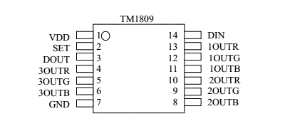
Pin function definition
| Pin number | symbol | Pin name | Instructions |
| 1 | VDD | Logic power supply | 5V±10% |
| 2 | SET | Mode setting | Connected to VDD: low speed mode; Hang in the air; High speed mode |
| 3 | DOUT | Data output | Display data cascade output |
| 4 | 3OUTR | LED driver output | 3rd Red PWM control output |
| 5 | 3OUTG | LED driver output | 3rd Green PWM control output |
| 6 | 3OUTB | LED driver output | 3rd Blue PWM control output |
| 7 | GND | logically | systematically |
| 8 | 2OUTB | LED driver output | 2nd Blue PWM control output |
| 9 | 2OUTG | LED driver output | 2nd Green PWM control output |
| 10 | 2OUTR | LED driver output | 2nd Red PWM control output |
| 11 | 1OUTB | LED driver output | 1st Blue PWM control output |
| 12 | 1OUTG | LED driver output | 1st Green PWM control output |
| 13 | 1OUTR | LED driver output | 1st Red PWM control output |
| 14 | DIN | Data entry | Display data entry |
Power supply configuration

The resistance value of R1~R12 can be adjusted according to the number of leds connected to the OUT port. It is recommended that RI and RO be connected with 200~500 ohm resistors for signal isolation to prevent the influence of the next level chip damage on the upper level.
TM1809 can be configured as 6~24V voltage supply, but according to the input voltage, should be configured with different power supply resistance, the resistance value R list is as follows:
| R supply voltage | It is recommended that a resistance be connected between the power interface and the VDD |
| 6V | 330 |
| 9V | 2.3K |
| 12V | 4.5K |
| 24V | 12K |
If you're not sure which IC is best for your project or need help with layout configuration, please call us at LIKELIGHT:+86-755-23328395, email :contact@like-light.com.We can provide you with complete design and manufacturing services to meet your specific needs and requirements.