How to Plan a 5V Addressable RGB LED Strip: Power Zones, Pixel Mapping and IP30 Limits
A commercial pixel-strip failure often appears only after installation: the first pixels look correct, the far end shifts colour, and an animation runs in the wrong sequence. Those symptoms can share one cause or come from separate power, data and mapping errors.
This guide uses the published LIKELIGHT strip facts to show what can be decided now, what must be measured on a sample, and how to commission the system without turning a product-page number into an unsupported project limit.
Published product facts
| Published item | Value |
|---|---|
| Model | L-S-SK6812-RGB-10060 |
| Input | DC5V |
| Published power entry | 18W; unit boundary requires confirmation |
| PCB | 10mm, black or white |
| Standard length | 5m |
| Beam / protection | 120 degrees / IP30 |
Diagnose colour shift before changing the animation
If red remains stable while blue or mixed colours weaken toward the far end, inspect loaded voltage before rewriting the programme. If every colour is bright but the chase order is wrong, inspect data direction and pixel mapping instead. Separating these symptoms avoids treating an electrical problem as a software problem.
This strip is not the first choice for an exposed wet location because the published version is IP30. It is better evaluated for protected indoor displays, profiles and equipment where the strip, controller and connections remain dry and serviceable.
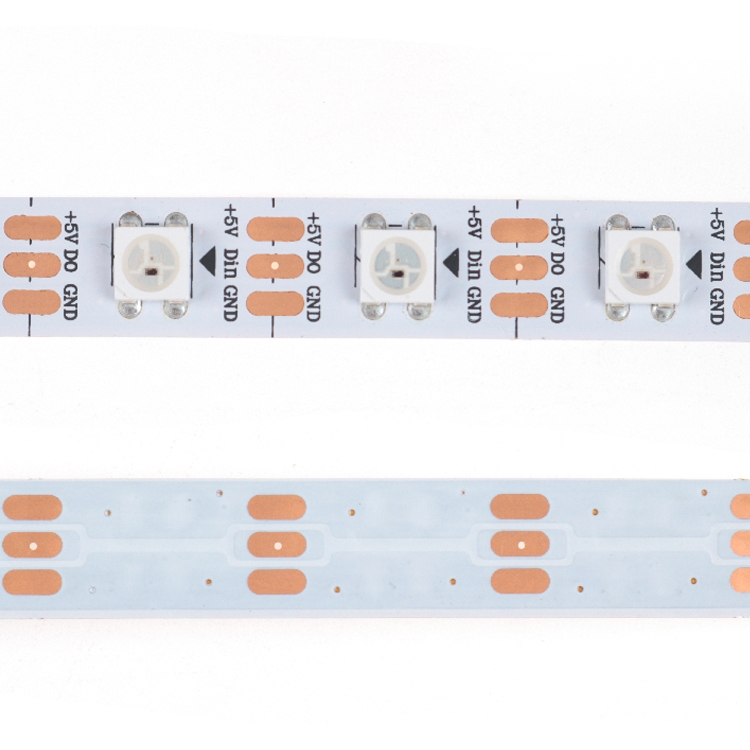
Read the published configuration without inventing density
The page publishes model L-S-SK6812-RGB-10060, DC5V input, a 10mm black or white PCB, a 5m standard length, a 120-degree beam and IP30. The product name includes 60 LEDs, but the structured page does not state an unambiguous per-metre density, so this article does not calculate LED pitch from that number.
The title mentions SK6812 and WS2812B while the structured IC field identifies SK6812-RGB-10060. Freeze the exact IC, colour order and data timing on the approved sample before the controller file and replacement stock are released.
Treat the 18W entry as evidence with a unit boundary
The page publishes DC5V and 18W. Dividing those entries gives 18W / 5V = 3.6A as a theoretical current for the same stated electrical unit. However, the page also lists a 5m standard length without clarifying whether 18W applies per metre, per reel or to another configuration, so 3.6A must not be used as the final supply size until the unit is confirmed.
Measure the approved sample while it runs the brightest intended content, then divide the installation into fused and serviceable power zones. A reel is not a complete installed system: cable length, conductor size, connector resistance, supply location and controller ground reference all affect the loaded voltage seen by the pixels.
Project selection table
| Project condition | Decision direction | Why |
|---|---|---|
| Far-end colour weakens | Measure loaded voltage first | The fault can be in distribution rather than animation. |
| Chase order is wrong | Check data direction and mapping | Bright pixels with wrong order indicate a data issue. |
| Protected indoor profile | Suitable evaluation direction | IP30 and service access can be planned. |
| Wet or exposed site | Choose another protected configuration | IP30 is not an outdoor wet-system approval. |
| Power supply sizing | Confirm the 18W unit and measure a sample | The page does not identify per-metre or per-reel scope. |
| Third-party controller | Freeze IC, colour order and timing | The title and structured IC wording must match the released sample. |
Map cascade pixels instead of assigning assumed DMX addresses
SK6812 and WS2812B are cascade-pixel families. The useful planning terms are pixel count, data direction, colour order, controller-port allocation and content mapping. Individual DMX addresses are relevant only when an upstream controller deliberately maps these pixels into DMX or Art-Net channels.
Commission one short zone first with a numbered chase and solid red, green, blue and white test frames. Record the first pixel, last pixel, physical direction and controller output; this reveals reversed data, wrong colour order and mapping offsets before the full display is connected.
Design the 10mm PCB into the mechanical system
The published 10mm PCB width affects aluminium-profile selection, clip clearance, corner handling and connector choice. A profile that pinches the PCB or forces a sharp bend can create a failure even when the electrical plan is correct.
The 120-degree beam describes the LED emission geometry, not the finished diffuser result. Channel depth, cover transmission, distance to the viewing surface and pixel spacing determine whether viewers see a continuous line or separate points.
Where this LIKELIGHT strip fits
The published combination of DC5V, a 10mm black or white PCB, 5m standard length, 120-degree beam and IP30 can be evaluated for protected retail displays, studio scenery, hospitality details and indoor programmable profiles where individual effects and maintenance access matter.
It is not a priority choice for wet outdoor installation, for a project that needs an unverified fixed LED pitch, or for a design whose power zones cannot be measured and accessed. LIKELIGHT can freeze the exact IC option and sample wiring before bulk production.
Suitable when
- Protected retail, studio and hospitality displays
- Projects with accessible DC5V power zones
- Controller workflows that can be sample-tested
Re-evaluate when
- Wet exposed installation using IP30
- Supply sizing based on an assumed 18W/m
- Unverified IC and colour-order substitution
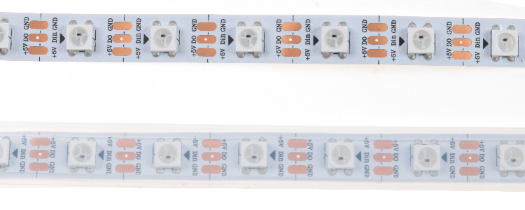
Information that turns a quotation into a wiring plan
Provide the total length, each zone length, profile drawing, closest viewing distance, intended animation, controller model, available DC5V supplies, cable routes, connector direction, dry or exposed environment, PCB colour, quantity and sample schedule.
These inputs allow pixel mapping, power zones and the mechanical connection method to be evaluated together. They also define which measurements must be recorded on the sample before the project quantity is released.
- Total and zone lengths
- Profile and mounting drawing
- Viewing distance and content
- Controller and DC5V supplies
- Cable and connector direction
- Environment, PCB colour, quantity and schedule
Frequently asked questions
Does 18W mean 18W per metre?
The current structured page does not define that unit, so confirm it before supply sizing.
Is every pixel assigned a DMX address?
Not inherently. This is a cascade-pixel system unless an upstream controller maps it to DMX or Art-Net.
Can IP30 be used outdoors?
This published version is intended for protected conditions; exposed outdoor use needs a suitable confirmed protection configuration.
Why test red, green, blue and white?
The sequence separates colour-order, data and loaded-voltage faults during commissioning.